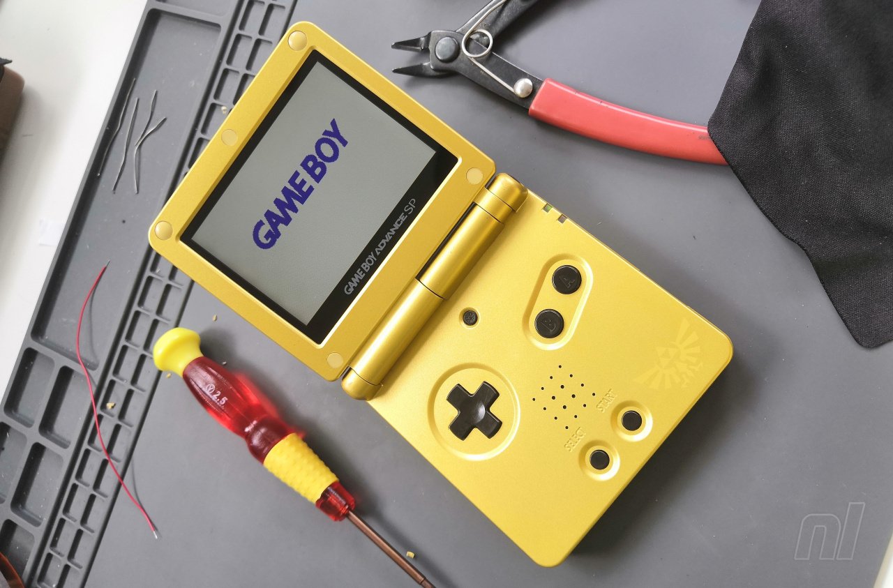
The Game Boy line of consoles may be old news to Nintendo, but that doesn't mean it isn't still evolving. Fan-made modifications are appearing all of the time which help augment and improve the tech which makes these handhelds tick, and one of the latest upgrades is a new IPS screen for the Game Boy Advance SP.
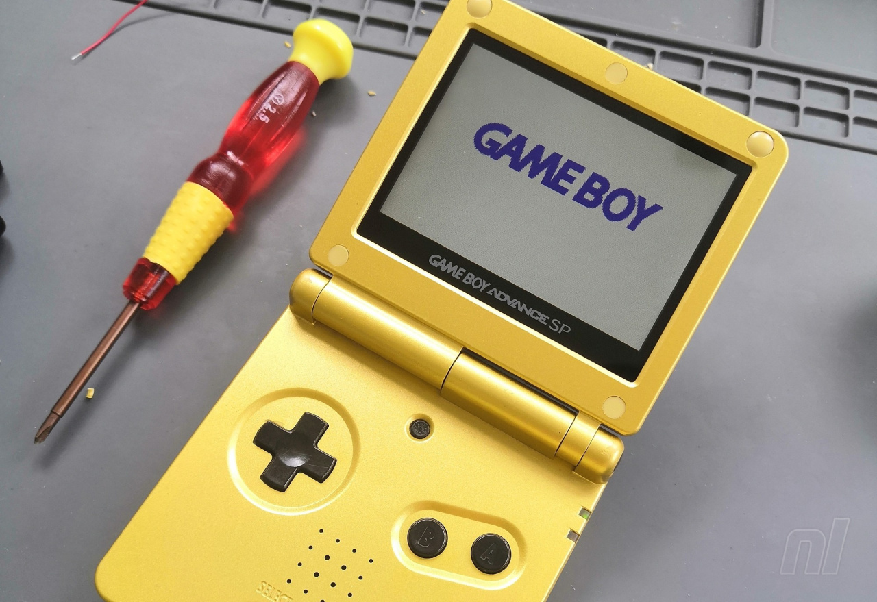
In this article, we are going to be looking at installing a new “IPS V2” replacement screen kit in a Game Boy Advance SP. These screens are slightly larger than the original display and feature bold, vibrant colours and adjustable levels of brightness. They really do look amazing!
 Watch on YouTube
Subscribe to Nintendo Life on YouTube846k
This guide is specific to the AGS-001 model of the SP, with the front-lit screen. Technically, the kits could be used to replace the screens in the backlit AGS-101 model using a different method, but honestly, those are best left as they are: pixel perfection.
The AGS-001 Game Boy Advance SP may have been the first-ever Game Boy with a front-lit screen, but compared to modern backlit displays, it leaves a lot to be desired in terms of brightness, clarity and vibrance.
IPS screens have been available for a little while now for original Game Boy Advance consoles, and now there are dedicated kits available for GBA SP, coming with a pre-fitted glass lens, eliminating those pesky bits of dust between screen and lens that are the bane of many a modder!
How To Fit An IPS Screen To Your GBA SP
The Kit
The kit itself is relatively simple and very satisfying to fit, although some cutting of the shell is required to make room for the new screen and a little soldering is necessary if you want to have control over the screen’s brightness (this is entirely optional, however). There are lots of sellers currently on eBay with these V2 IPS kits; the one in this article was ordered direct from China.
In the kit we bought, we got the IPS screen assembly with glass lens pre-attached, a ribbon cable with the control board for the screen at one end, a piece of insulating film for the back of the screen, a foam insert, a piece of double-sided tape, and a piece of wire pre-soldered at ends for the brightness control. The kit also contained a crosshead screwdriver and a tri-wing security screwdriver to help open the shell.
Not every kit will come with the exact same parts, and always make sure the seller has a good reputation before placing an order.
NOTE: We've noticed that these new IPS screens are quite power-hungry, so if your existing 600mAh Game Boy Advance battery is a bit long in the tooth, you might find stamina is low. You can either purchase a new 600mAh battery or upgrade to an aftermarket 850mAh battery, which are available on eBay for less than $10.
Equipment
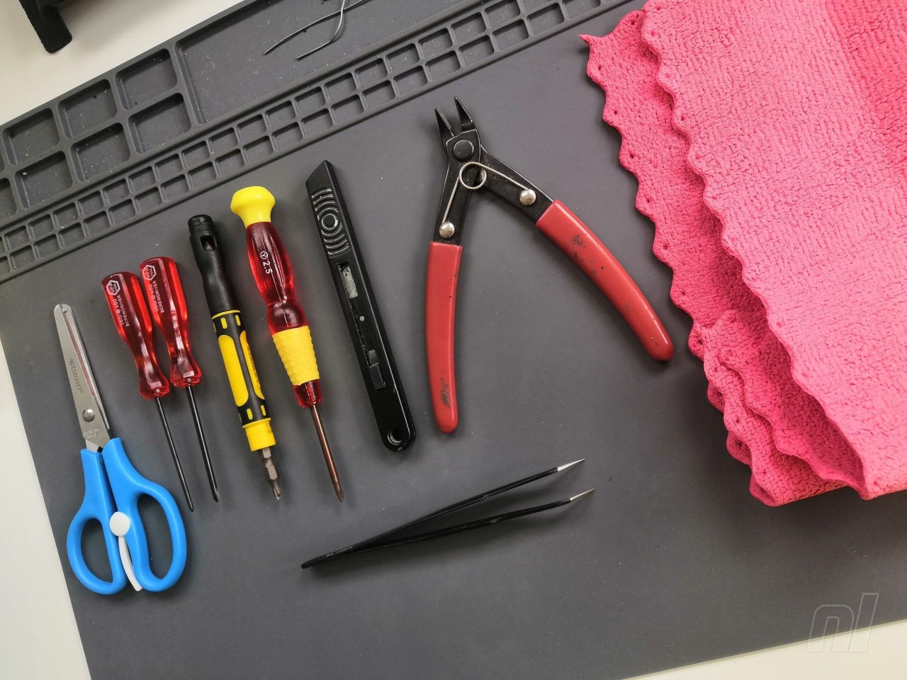
Tools recommended for installing the kit are the aforementioned screwdrivers (be warned the quality of these isn’t great, so if you have better quality ones you’ll find the job easier) and cutting tools for removing the plastic. A Dremel-type power tool is quick and easy, but not everyone has access to one of those, so in this guide we'll focus on using a pair of side cutters and a sharp craft knife. Having a knife with a good point on it is also useful when removing the screw caps in the top of the shell. In addition to this, a pair of scissors, some tweezers and a microfibre cloth will prove useful.
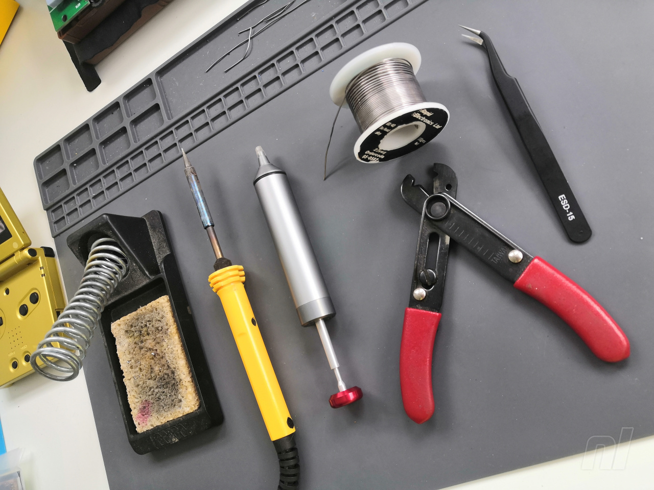
It is entirely possible to install the screen with no soldering at all; however, if you’re feeling adventurous there’s a simple one-wire soldering job that will allow you to adjust the brightness of your display – and believe us, it’s a great feature. You’ll need a low wattage soldering iron with a stand and some soft solder, and if you have access to flux, a solder sucker and a pair of wire strippers – they’ll make for an easier job.
Preparation And Disassembly
Work on a soft surface free from debris; you don’t want to scratch the top of your console when you flip it over. The microfibre cloth is ideal for this.
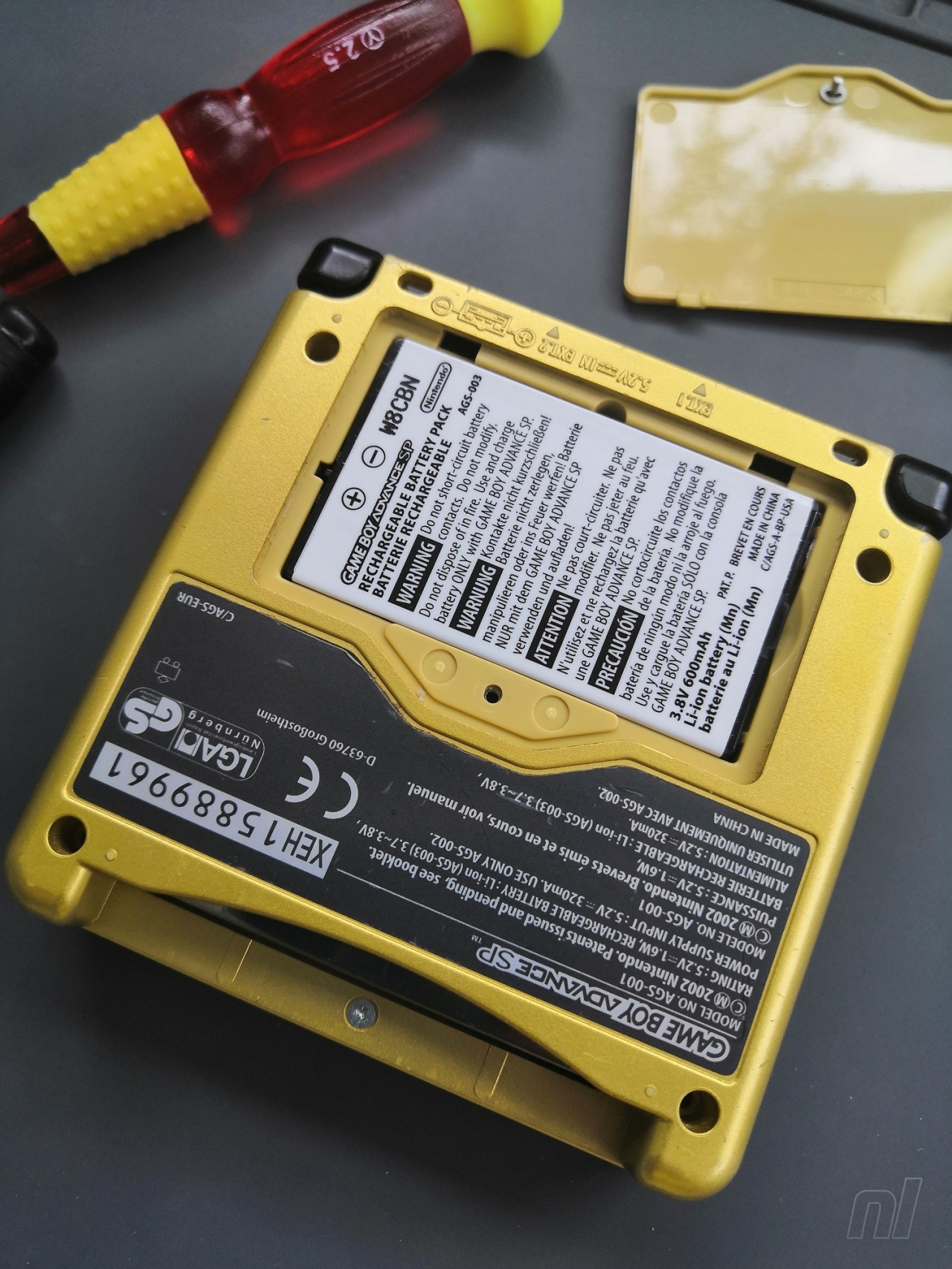
Turn your Game Boy upside down, undo the crosshead screw on the battery cover and remove it from the console. Take out the battery; one end will lift allowing for easy removal.
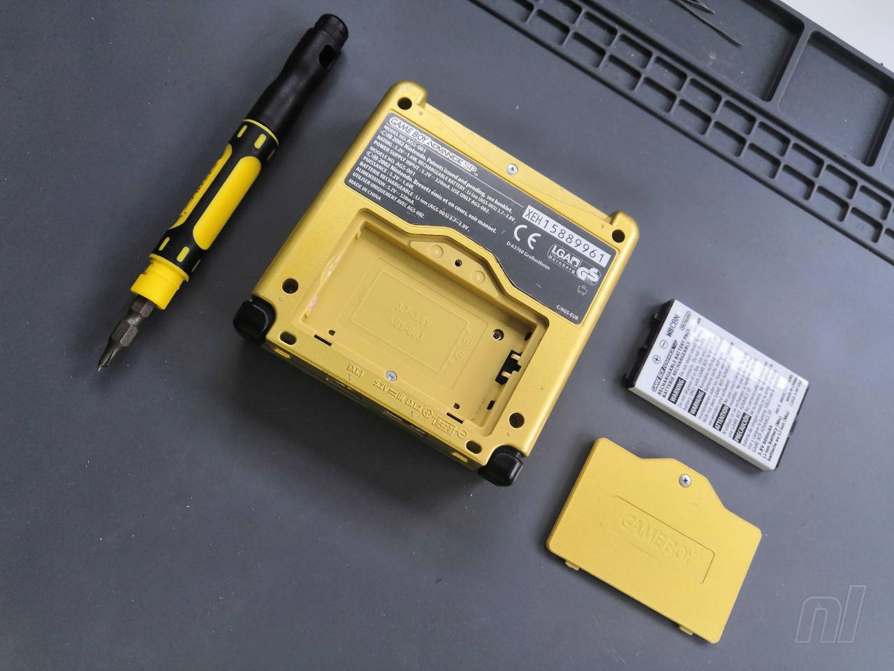
Undo the four tri-wing at the corners as well as the one that was under the battery and another at the opening of the cartridge slot. It’s a good idea to keep your screws organised as you go, as you’ll encounter more along the way – and they’re all different.
Remove the back shell of the console and put it to one side. It should lift off easily, and the L and R buttons should remain attached to it.
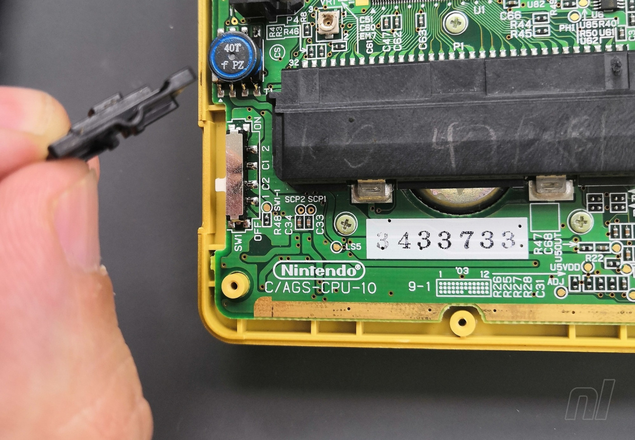
Lift out the plastic power switch piece and keep it somewhere safe.
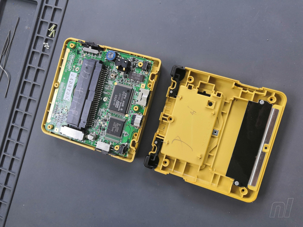
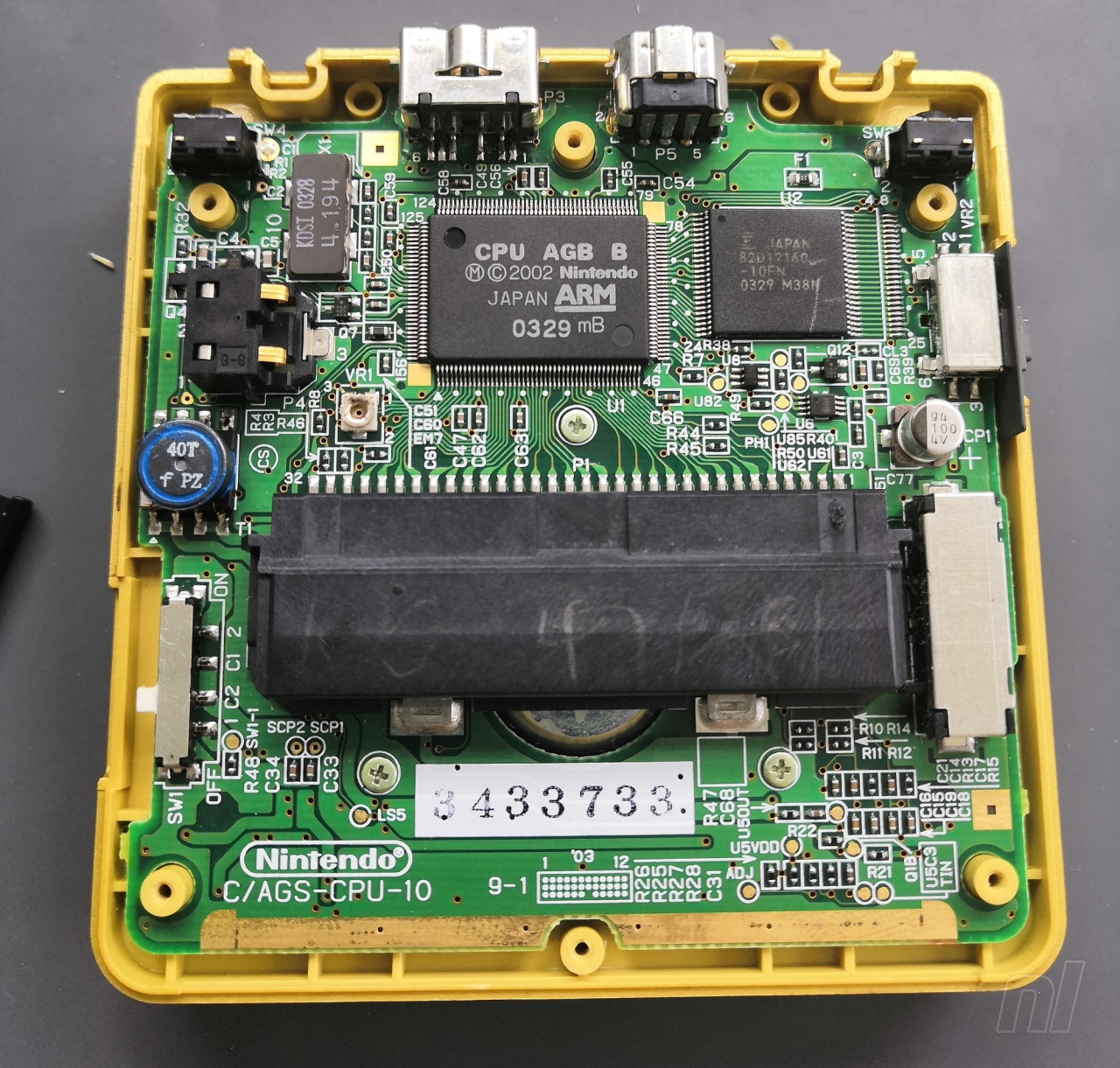
Take out the three crosshead screws holding the motherboard, which you’ll then need to carefully lift in order to access the ribbon cable where the screen is connected.
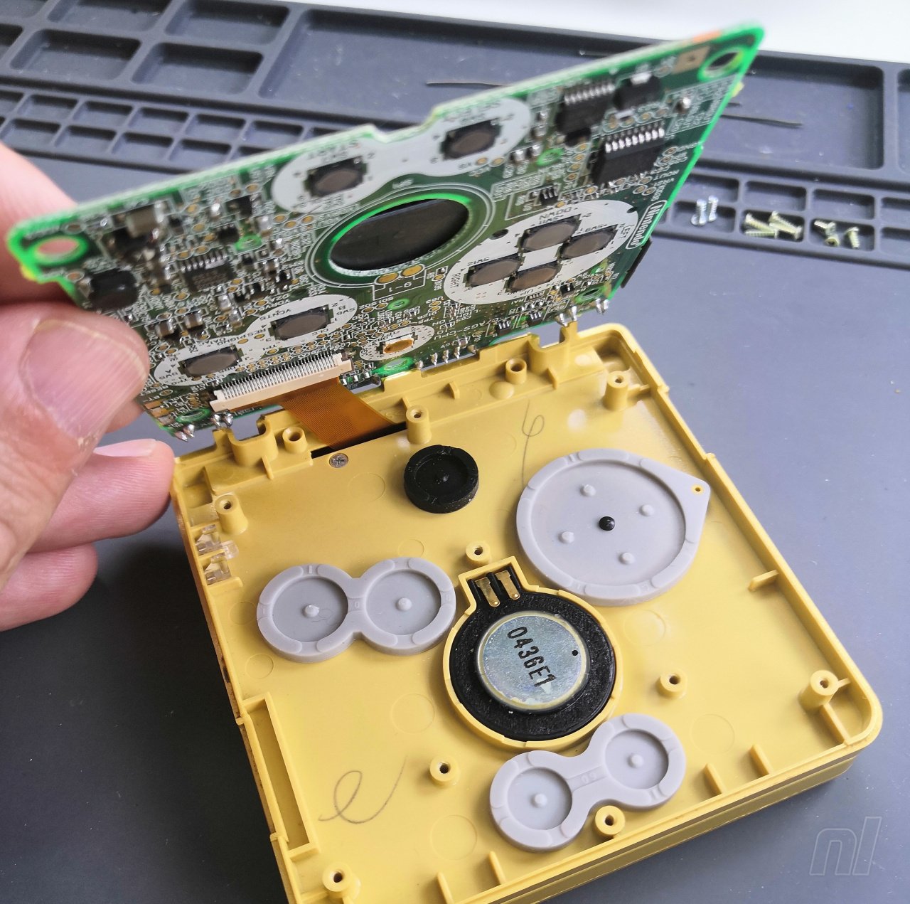
Remove all the silicone pads, buttons and the speaker, as well as the protective circular fabric piece from the speaker opening.
To remove the ribbon cable from the motherboard, undo the locking mechanism by carefully unclipping the plastic retaining strip at each side. It should easily unclip with a fingernail or a spudger-type tool.
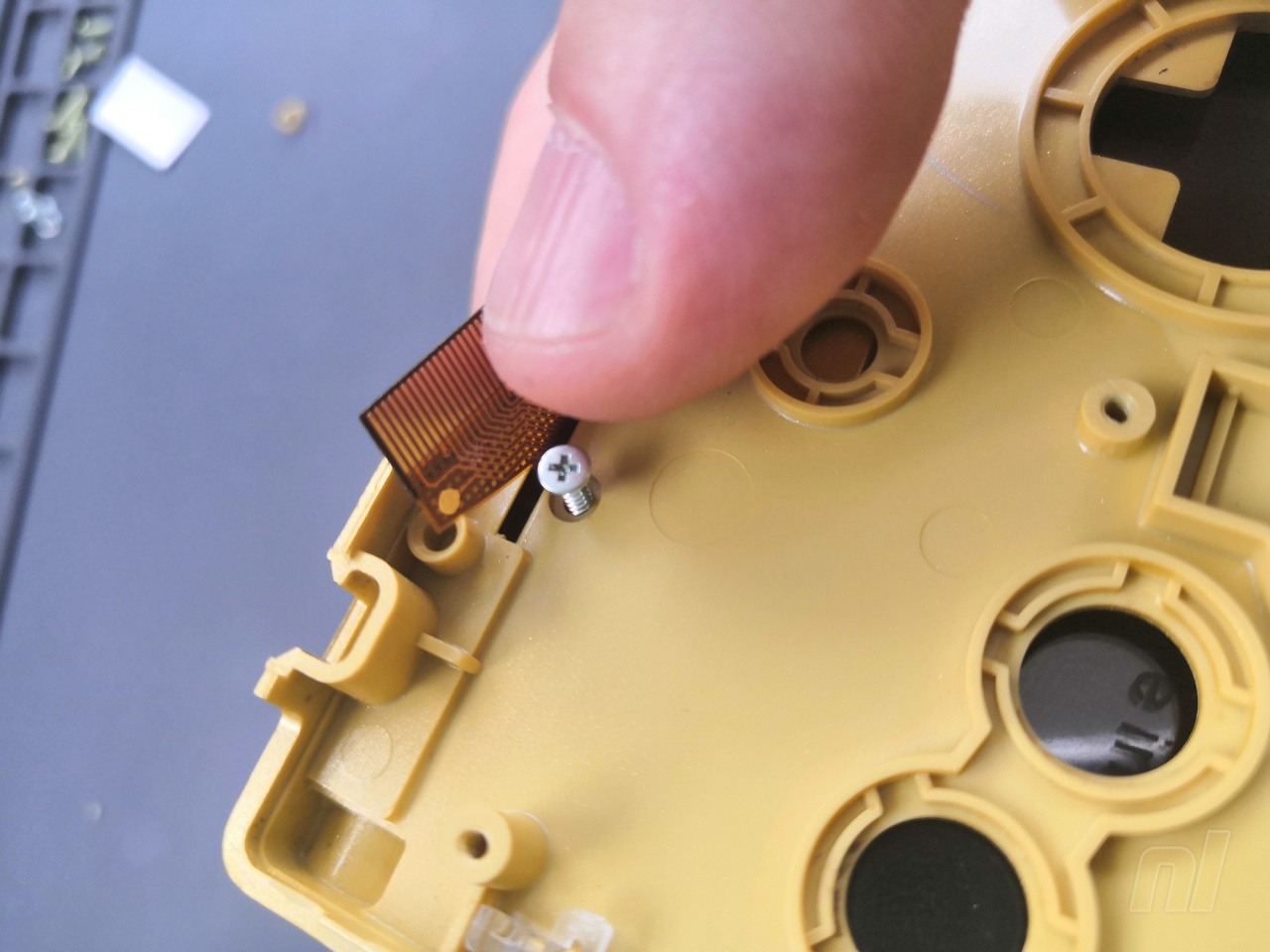
With the motherboard now out of the shell, remove the hinge cap by lifting the ribbon and removing the crosshead screw you’ll find beneath it.
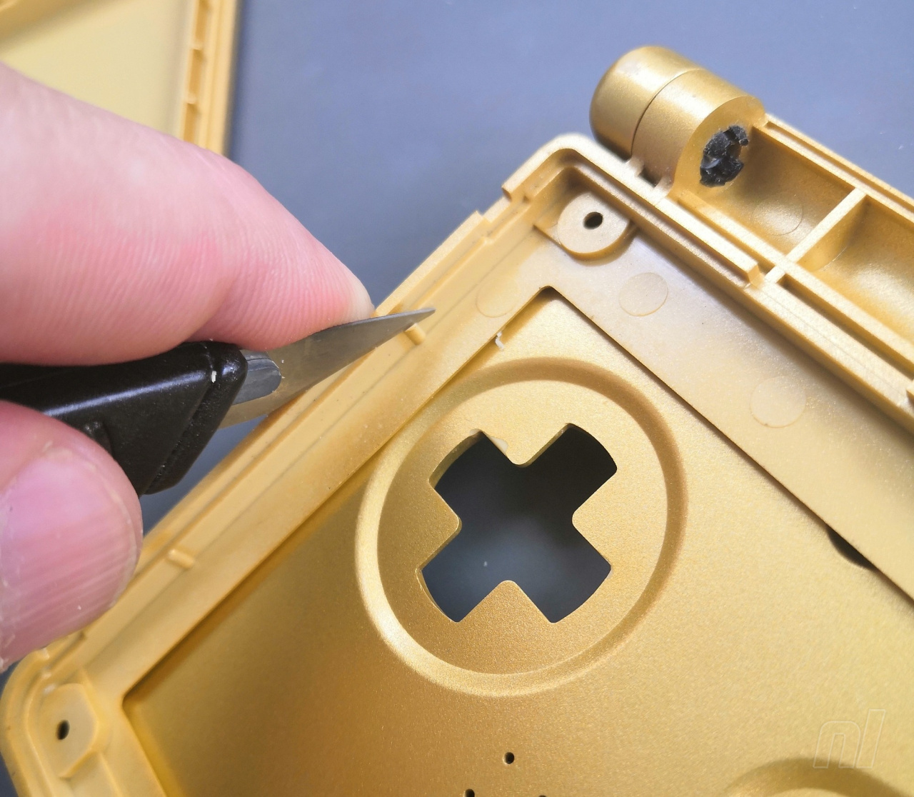
Next, you have five screws holding the top assembly together that are hidden beneath a set of silicone inserts. Remove the inserts with a sharp point, such as your knife, being very careful not to cut into the silicone or scratch the shell. It’s a delicate job; be patient. Try to move the point down into a small gap and then carefully lever out the insert.
Once the inserts are gone, you’ll have five tri-wing screws to remove.
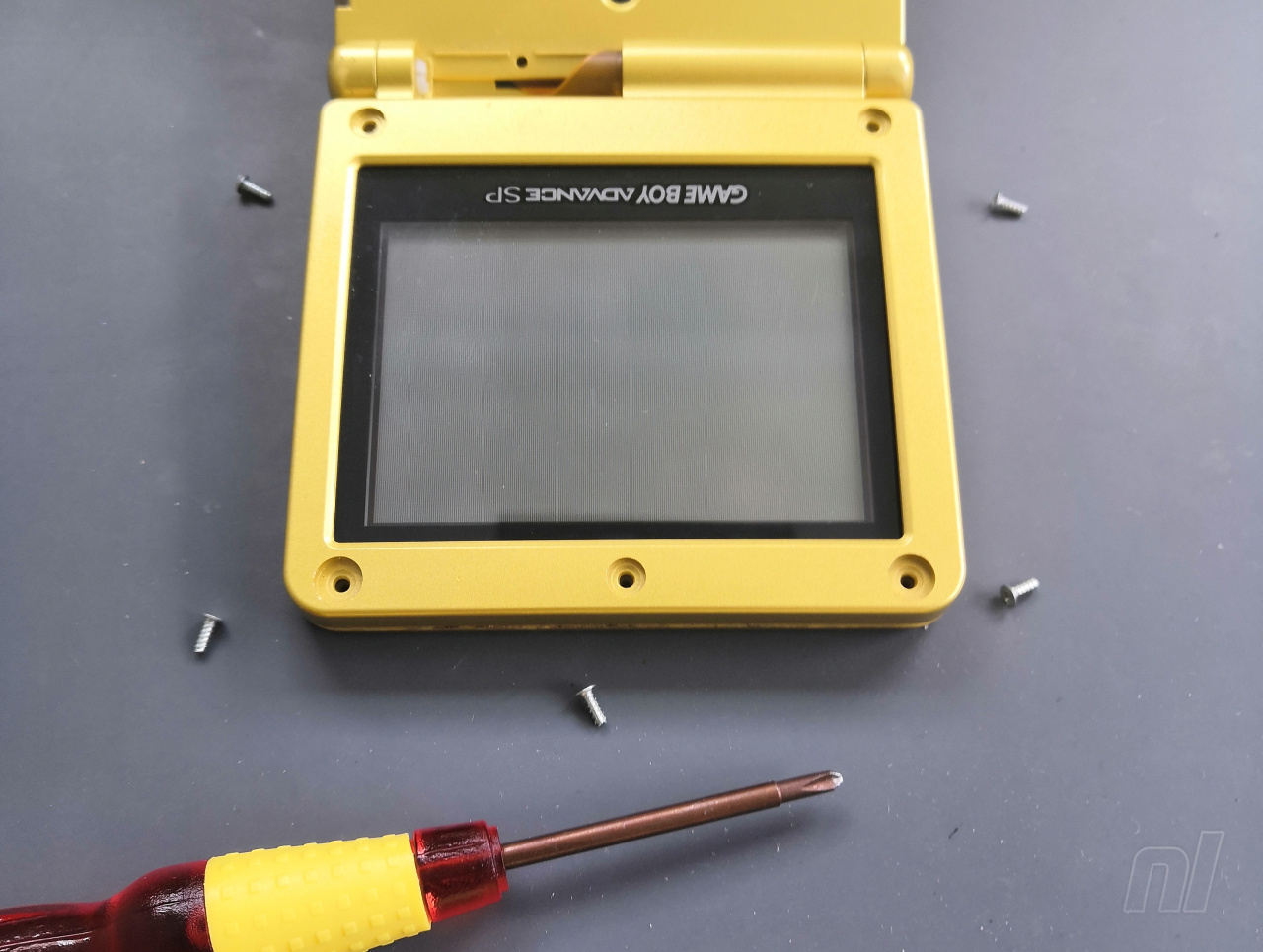
Now, close the hinge and remove the top of the shell. This is the part we’ll need to cut in order to accommodate the new, larger screen.
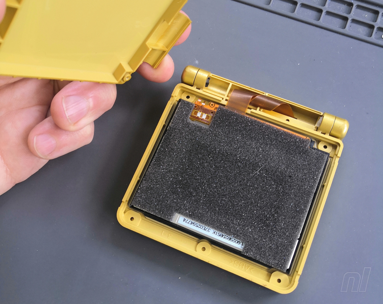
Now carefully slide out the ribbon from the slot in the shell and remove the existing screen assembly (it should just lift out).
Cutting The Shell
Looking at the inside of the top shell piece, there are two rails that currently secure the existing screen in place. To allow the new screen to fit, one of these rails needs removing to make space for it. This is the part where the lens doesn’t overlap the edge of the screen, on the left-hand side as you would look at the screen when the console is open, with the hinge part pointing down. You can see how with the plastic rail still in place, the left side of the screen won’t fit in the housing.
If you have a Dremel-type cutting tool, this may well be quicker and easier, but mistakes happen easily when working with power tools, so if you use this method, be sure to work carefully and slowly.
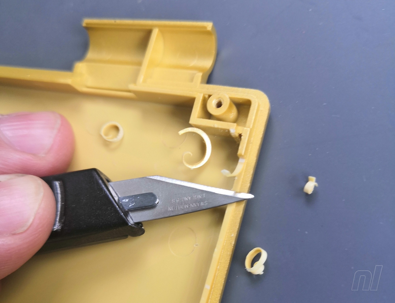
For this one, we used side cutters and a craft knife. We used the side cutters to gradually nibble away at the plastic using a small bit at a time. These small plastic parts will fly in all directions, so eye protection is advised; also try to point it away from yourself whenever possible.
Further into this job, you may want to alternate between the cutters and the knife; when using the knife cut away from yourself and NEVER allow your fingers to sit in the path of the blade. These knives are very sharp, and it is very easy to cut yourself if you are not careful.
For the final stage and to neaten up your cutting, slice a small layer at a time off with the knife, and once you reach the lowest point you can drag the blade across the surface to scrape away the last remaining bumps and achieve a relatively smooth surface.
Preparing The New Screen
Place the insulating film as neatly as you can on the back; making sure you cover the edges at the corner where the tab is situated for attaching the control board.
Attach the tab to the socket on the control board by lining it up and applying a little pressure until you feel a click.
Loop the ribbon around carefully to allow you to flip over the control board so it sits on the screen. Use a small amount of double-sided tape (we used half of the piece from the kit) to secure it in place, being careful to keep the edge of the control board parallel to the edge of the screen housing.
Check that the screen assembly drops into the frame on the housing (the part with the rectangular opening so you can see the screen). At this stage, we’ll leave the protective film in place. Usually, it will drop straight into place but in this case, there was a little resistance. It’s never a good idea to force these things and have the assembly under strain so if the fit is too tight, carefully use a knife to reduce the profile of the four raised areas inside the frame housing and make a bit more room for the screen.
You don’t want to remove too much, so it moves around, just try to achieve a snug fit without having to force it. Better to remove a small amount at a time and keep checking it.
Once the screen drops comfortably into the housing, gently place the top of the shell in place (it won’t close up properly yet, don’t force it!) and take note of the plastic area that is keeping the top shell from closing up properly; this is the part that will end up near the control board on the back of the screen. Safely trim this part away with the craft knife, removing a thin layer at a time and being careful not to cut any of the outside edge of the casing.
Gently test the fit and remove more plastic as necessary until the lid fits on comfortably without needing to squeeze it shut. You don’t want to be applying any pressure on the LCD or control board as this could permanently damage the display.
Installing The Screen
Once the lid is trimmed and will fit correctly, you have two other jobs to do. Firstly, loop the ribbon over once and feed the tip through the slot in the shell, just like the old screen.
Next, reattach the hinge cap piece; this will help keep the ribbon in place. You can put the lid of the shell in place but don’t screw it together yet.
Hold the shell together so the screen doesn’t drop out, hold the cap in place and use the crosshead screw to secure it.
A note on reinserting screws into plastic: there will be a thread cut into the plastic from last time the screw was fitted, that you want the screw to go back into. If you just screw straight in, you run the risk of it cutting a new thread and shearing off the plastic, preventing a secure fit. To avoid this happening, first turn the screw anticlockwise until you feel a little “pop” as the screw locates in the threaded hole. Then, turn clockwise and it should screw into place with little resistance. Turn the screw until it is in place and no more – avoid overtightening as, again, this could permanently damage the plastic and cause an unsatisfactory fit.
Brightness Control (Optional)
You need to prepare two points with solder. Solder will only stick to hot metal, so the process involves heating the pad first with the tip of the soldering iron, melting a small amount of solder onto the pad while the iron is in place, and briefly leaving the iron in place afterwards to allow the solder to flow properly. The whole process will only take a few seconds and if you get it right it will sit like a tiny dome shape on the metal contact you soldered to.
First, melt a little solder onto the circular contact point near the end of the ribbon cable, then melt another little bit of solder onto the point marked Q12B on the motherboard. If you have flux put it onto the points first and it will help the solder flow correctly into place.
The wire that comes with the kit is quite long so it will reach easily; the only issue is that it can make it difficult to reassemble without the wire getting in the way. We found it easier to use a shorter wire, but that involves “stripping” and “tinning” the wire before attaching it. The one that comes with the kit is stripped and tinned already so you may prefer to use that one as it is. Stripping the wire involves cutting it to length and then removing a little bit of the plastic insulation at the end to expose the metal wire inside. It can be tricky to get used to, so we suggest practising on the long wire rather than cutting to size then having your first attempt! Tinning simply involves melting a little solder onto the end of the wire. Again, heat it first, add a little solder and let it flow. The exposed metal tip only needs to be a few millimetres long, so cut it down to size after tinning if you need to.
Then you need to attach the wire. If you’ve prepared correctly this should be easy. Hold the wire so that the end lines up with the contact point you want to attach it to. Gently reheat with the soldering iron; the solder on the end of the wire and on the contact will melt and join. Move the soldering iron away and hold the wire steadily in place while the melted solder cools and sets. It will provide a nice secure join. Repeat with the other point and the other end of the wire.
Reassembly
Reattaching the ribbon into the motherboard can be awkward. Gently pull the ribbon through the gap in the shell to give you a little room to work with but of course don’t put any strain on it as it’s very delicate. If you rip the ribbon, you’ll need a whole new kit, so take it slowly!
Slot the end of the ribbon into the opening on the motherboard and clip the two ends of the plastic retainer back in place. Do a visual check to make sure the ribbon is in straight and both clips are secured. If they aren’t, simply undo the clips and try again until it fits.
Make sure your wire is clear of the white areas around the buttons on the motherboard as this will stop it from closing properly. You can carefully tape it in place to make reassembly much easier.
Put all your buttons, speaker and silicone parts in place before locating the motherboard in position and securing it with the three crosshead screws.
Put the rear shell back on, being sure to put the power switch piece back in place first.
You can just attach two of the six tri-wing screws for now (at the cartridge opening and in the battery compartment) in case you end up needing to open it back up for troubleshooting. Reinsert the battery (either your original 600mAh battery or a higher-capacity 850mAh one) and put the battery cover in place, securing it with your crosshead screwdriver.
Now the bottom half is secure, it’s time to finish the screen installation. Sit the console flat and lift off the lid. Carefully lift out the screen assembly and peel off the protective film.
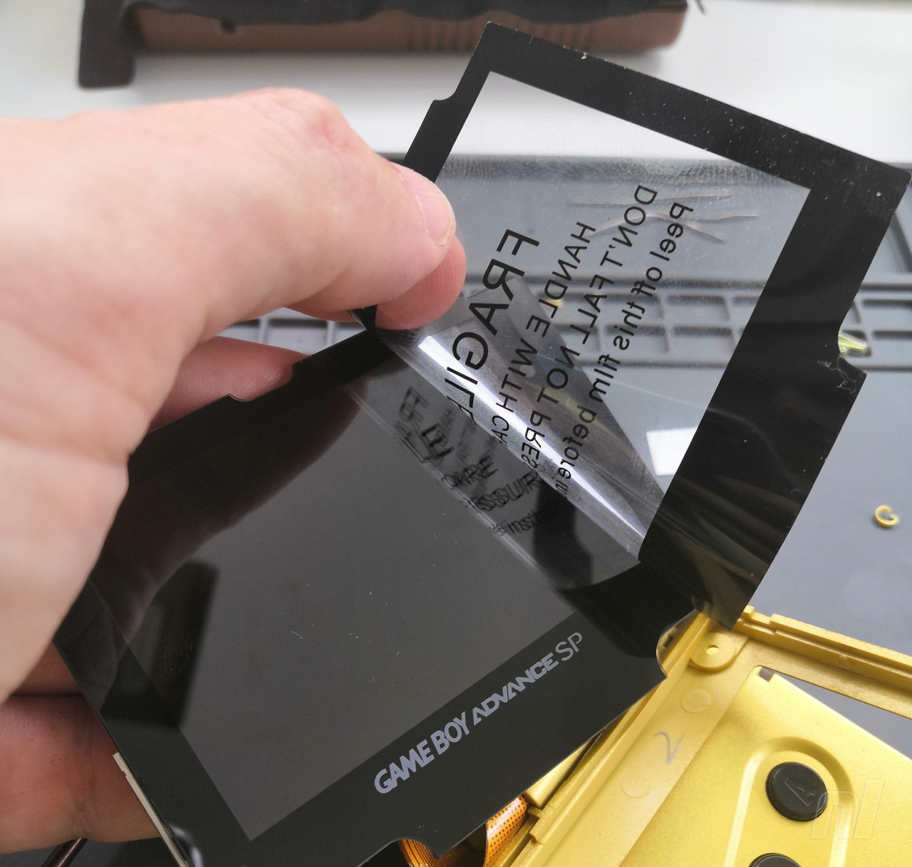
Avoid getting fingerprints on it, especially at the edge, and lower it back in place.
Use scissors to cut out a small section of the foam piece and use the rest of your double-sided tape to secure it to the back of the screen. We found using the entire foam piece generates a bit too much pressure and can cause the top half to bulge a bit; we don’t want that!
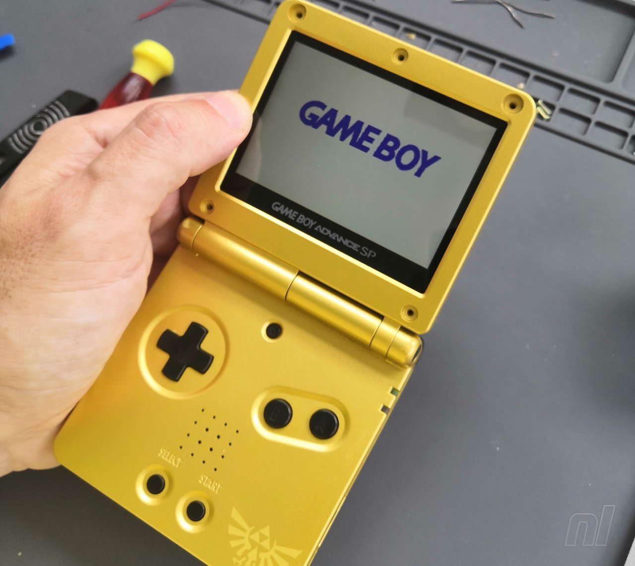
Put the lid of the shell back on, carefully lift open the hinged top half of the console, move the volume slider up if necessary, and switch on the console to test it. You should get the “GAME BOY” splash screen and the sound should come out of the speaker. If that works, well done!
If not, don’t worry. Make sure the ribbon cable is seated correctly in the retaining bracket and secured in place. Undo and reseat it if necessary. If that doesn’t help, make sure your soldering is secure and there are no “bridges” with unwanted solder connecting the wire to other points on the board. Make sure the wire isn’t being pinched when the unit is closed.
If the screen works, try pressing the brightness button in the middle top of the control panel. The brightness should increase with each successive press until it goes back to a dim display and starts to increase again.
Now switch it off, put a game in for testing and turn it back on to make sure all the buttons work. Something like Street Fighter Alpha 3 is ideal as you can check all the buttons easily. Make sure the D-pad, A, B, L, R, start, select and brightness control buttons all respond correctly before securing all the remaining screws in place. If they don’t work properly, open the bottom half back up and make sure your wire isn’t interfering with the location of any of the buttons.
Once everything is tested and working, reinsert the five tri-wing screws to secure the top half together.
It’s worth a quick check to make sure it’s all still working before you put your silicone pads back in place in the top half to hide the screws again, as we know how tricky these are to remove!
Reinsert your remaining four tri-wing screws into the bottom of the unit, and you’re all done. As we mentioned before, you might find that battery life is reduced due to the demands of the new screen, so an upgrade might be your next job.
Happy gaming, and be sure to visit Joe Bleeps for more cool mod videos!


Comments 33
Very cool, but a lot of work, I prefer to leave my game boy without the IPS screen (if I had a gameboy,)
I'll just play GBA games on my NDS, thanks. This seems like an extraordinary amount of fiddly work. Kudos to anyone who pulls it off, though.
Scrolling though this guide makes me think I really should just buy a modded GBA off eBay or Etsy! (no complaints about the guide, it looks great and highly detailed....just too much work for me to take on myself)
@joebleeps with the great tutorial pictures Nice work!
I did something similar with my original game boy advance a couple years back, highly recommend as it actually not that fiddly
@Camo-joe r/Gameboy on Reddit has tons of users posting their work and tutorials on how to mod Game Boy screens. I haven't personally modded any of my systems, but seeing some of the work they do is fascinating.
Fantastic guide and well worth it if you play the GBA a lot and replacement batteries are actually easy to come by for it some with longer life than the originals. This is something I would rather leave to someone who has experience in doing it more with making the physical alterations to the shell as I am personally a bit heavy handed with that kind of stuff and knowing my luck would damage the case personaly I would rather just use an original DS as they already have a good quality screen and are cheap to pick up.
Just shove it in REAL hard
Now what about an OLED Touch screen on Switch??
I kinda want a bigger screen for GBA games.
I find this kind of stuff really interesting, similarly to homebrew. The process of learning how the machine was put together and how people have taken that knowledge to do interesting new things with it is really interesting. Great little article here.
Modding handhelds like this is something i've been getting into recently, it's a fair bit easier than it looks at first and it's nice to be able to recycle/upcycle old hardware. Making gameboy macros from old broken DS's has been most enjoyable as they have great screens and you can do a lit in terms of customization.
Lol I'll keep my ags101s in the state they are.
I recently replaced a 3DS shell and buttons, but these screen replacements seem a whole other level. Maybe one day I'll give it a go.
@Kriven gba micro is better.
Anyone who does this is factually and incontrovertibly stupid. Why go through all this work to play GBA games on a miniscule screen when you can just get a New 2DS XL and play them on a much bigger screen?
You cartridge fetishists need to have your heads examined. These games take up almost no space on an SD card and they are readily available.
@g_ruz I second the r/GameBoy community! There are some amazing looking projects coming out of that group. They've really been breathing some new life into old Game Boy models. I especially love seeing the Game Boy Pocket mods that the community comes up with regularly.
@TheWingedAvenger "Why go through all this work to play GBA games on a miniscule screen when you can just get a New 2DS XL and play them on a much bigger screen?"
1) Let's start with the obvious: GBA games aren't available to purchase and play on the Nintendo 2DS/3DS unless you were able to take advantage of the Ambassador program back in 2011.
2) Games don't look as pin sharp when blown up on a larger screen.
3) The people who tend to mod their consoles also tend to be hardcore hobbyists who are attached to their older hardware.
@nexx27 YES x 10000!
Before starting this project, I'd suggest reading the whole guide first. I know it seems like a lot, but it's fairly straightforward if you just take it one step at a time, especially if you know the context of each step (having read ahead). I appreciate all the work that went into the guide, even explaining things that are second nature to a modder, like how to not strip a screw thread.
I wish a guide like this was around when I modded my standard GBA last week! Well done Joe! I seriously appreciate the abundance of photos haha
@nexx27 I would totally do swap out my Switches screen for OLED one but no one makes them. I have been keeping my eye on screen makers and the like and there seems to be no talk of this. Also, OLED screens are expensive to make.
I’m sold. After replacing a iPad screen this looks pretty simple. Lots of steps but nothing special. I’ve got an old SEGA Nomad (the OG Switch) that I really want to mod though. A rechargeable battery and a better screen would make that worth the bulk.
@Ralizah Eh, for those that know this sort of thing it takes minutes. Now, I'm a woodworker, so I'm not touching it, but my friend who is an engineer could do it during his lunchbreak if he wanted lmao.
this was my project last summer and I can say that it deffinitely breathes new life in to your GBA.
https://puu.sh/FYiET/b5e841e62b.png
the left is an AGS-101 and the Right is the Funkyplaying V2 IPS
The IPS gives nice vibrant colors while the AGS-101 has nice scanlines. Pick your flavor!
@joebleeps Awesome guide, Joe! Epic read. So that’s what goes on behind the Instagram curtain…
One day – one day – I will get myself an old Game Boy and a set of proper tools, study your instructions until I can recite them backwards, lock myself in a workshop for a week, then throw away all the broken pieces and cry.
@Steven_the_2nd Are there any screens from other products, like car reverse camera screens, that are a similar dimension/voltage to the Switch?
@RogerFederer Agreed! Hopefully they do one on how to install battery holders in old games, or how to replace capacitors in legacy gaming hardware or whatever.
A guide on fixing up old hardware would be much appreciated!
Ill leave mine as is.
But what if you have the sponge bobmodel. You wouldnt need to do this right?
Looks like a good project for some slow days. ...I’m getting tired of transformers upgrade kits.
But does it adhere to the proper GBA color space? Because the official 101 does not. Like the DS Lite, all colors will be oversaturated. Barf.
I've also heard that some of these replacement screens have refresh issues.
The GB Micro does it right, so does the GB Player (IIRC) and the 3DS. The "phat" DS does too, but the contrast is a bit more washed out looking.
Nice guide! Last year, I found my old classic Gameboy in my parents basement and pimped with backlight and a new case. It's awesome!
For this guide here, I would actually suggest to buy a new case for the GBA instead of destroying the original one. It may be just me, but I like to have the option to go back to the original hardware if I want to, so I try to keep original components intact. The new cases are also quite cheap and you can go crazy on the colors
Show Comments
Leave A Comment
Hold on there, you need to login to post a comment...