In this unique one-off feature, esteemed Game Boy modder Joe Heaton — also known as Joeteach — takes us through an entire Game Boy custom job.
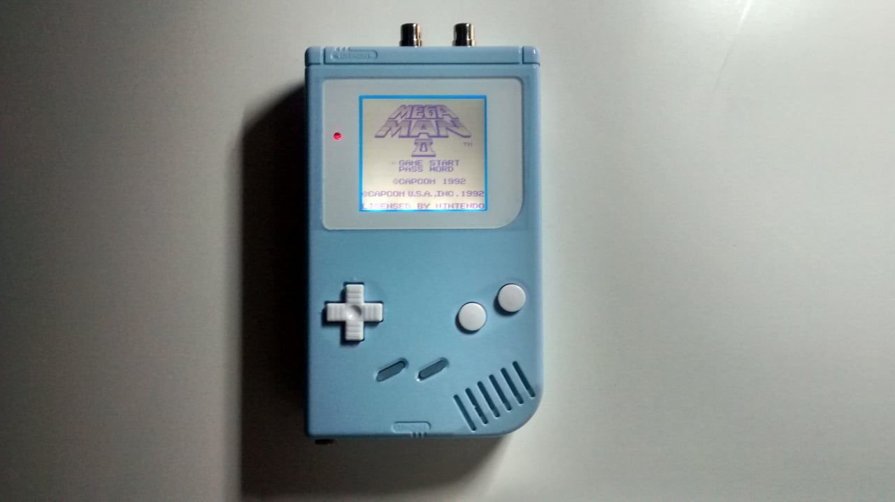
Over the last couple of years, since getting hooked on the Game Boy modification scene and sharing my creations on Instagram, I have been asked a lot of questions. People might want to know what it is I have done to the Game Boy, how it differs from the original, what that switch does or what that socket's for. They may want to know how I fitted something, what parts I used, where I got them from and how difficult it was. So I figured it's high time I talked through one of my projects, in this case the Baby Boy Blue created recently for Nintendo Life. I took photos throughout the process and have done my best to put into words how I went about reviving a tired old handheld into something unique.
I am no expert and am still learning as I go with the help of the online community. What follows is how I go about a typical project but it is not intended to be a definitive guide.
I started with a classic grey DMG-01 original Game Boy. It had no battery cover and wouldn't switch on. A quick clean-up of acid residue left behind on the battery contacts from a long dead power cell enabled the machine to spring back to life. There were a few vertical columns of dead pixels on the display too, but we'll come to that later. I dug out a spare battery cover from one of my many boxes of Game Boy bits and set to work.
Disassembly of the main unit requires a tri-wing screwdriver, and to separate the two halves a ribbon needs carefully unplugging from the back PCB. The battery cover acts as a handy tray for all the tiny screws. A regular Philips head screwdriver can then be used to remove the PCBs and the metal shielding from inside the housing. The LCD is held in place with a sticky frame to stop dust from getting into the display area and needs carefully teasing out once the screws are removed. Take it easy, you don't want to crack the LCD so early on! Battery contacts can easily be levered and slid out with the aid of a small flat head screwdriver. It helps to have a small plastic tub and a zip lock bag to put all your "guts" in while you work on the shell. The type you get your Chinese takeaway in are perfect for this so it's worth keeping those and washing them!
If a Game Boy is in good condition it's worth keeping it that way and I wouldn't encourage painting or further customizing other than new buttons or screen cover. In the case of this project it had seen better days and needed help. Pop off the screen cover from the back and it will leave an often dried-out residue that can be easily removed by scraping a razor-blade across the surface (mind your fingers!). I use a combination of baby wipes, kitchen roll, sticky stuff remover, an old toothbrush and a magic eraser to clean any dirt or marks off the shell. Don't use solvents! I use needle files to smooth out any dings or scratches from the edges and corners of the shell. A good rub down with scotchbrite or even a dishwashing scourer/sponge can be used to dull the surface ready for painting. If you leave it smooth and shiny the paint will just flake off.
This is the best stage for drilling any holes for switches or Prosound mods. This kind of mod is one of the most popular for the Game Boy and provides additional audio connections giving a cleaner, louder line-out compared to the standard headphone socket. For this project I installed a 3.5mm socket for a sound signal that can be controlled via the volume dial and a pair of RCA sockets for a direct line-out. Using a dremel type tool to create a small hole and gradually widen it to the right size in the right place is the best bet when starting out. I use a 6mm drill bit with my trusty cordless drill and have a jig I built to aid accuracy and speed up the process of getting these holes in the correct place. The 3.5mm socket needs a hole in the lower right of the front shell. I prefer to put the RCA sockets at the top of the front shell, between the screw posts (don't put them too close together; you need the plugs to connect without getting in the way of one another). There are other locations you can place these sockets, but these are the ones I prefer to use. It's worth a quick check and adjustment if needed at this stage to make sure your sockets fit in place before doing any soldering.
If you're going to paint then now is the time. I've not done that many paint jobs but patience is always the key to success. Keep the area well ventilated and build up in thin layers at a time, giving plenty of time to dry in between. Don't forget to spray from the back too otherwise you'll still have the original colour visible where the front and back shell join. I used Plasti Kote spray paint in this case (Baby Blue) and used a clear sealer spray over the top. Leave the paint to harden for a few days before putting your Game Boy back together. Again, it's all about patience.
Now back to that dodgy screen. I use a mains adapter I bought from eBay to power the unit without batteries, enabling me to work on the unit when it's out of its shell. There is a rubber strip just below the LCD; this needs carefully removing before fixing the dead pixel columns. Very carefully and sparingly, run a low wattage soldering iron over the ribbon below the LCD where the blank columns occur. In time, they will come back to life as the glue connecting the parts reheats and adheres once again. This may take a while, but it generally works well. Unfortunately if you have horizontal lines it isn't as easy to fix and you might want to look for another unit.
Now for the backlight. I used an ASM Retro V4 Density backlight kit from GameBoy Mods UK — there are many superior tutorials out there on how to install these so I'll keep it brief and add a few tips. Once you have lifted the LCD out from its frame with the aid of a razor-blade, carefully remove the top corner of the backing film from the glass. It's important to use a brand new razor-blade for this. This is just to start off until you have enough to grip between your thumb and forefinger. Removing the film with your fingers and thumbs is often a difficult process; sometimes it will peel easily but usually it's more stubborn. Be patient to avoid cracking the LCD or tearing a ribbon. Any residue left behind can be removed with a microfibre cloth and a bit of patience. As I was doing a "biverted" backlight on this unit (inverting the image twice for a regular, sharper picture) I needed to install the polarized film for an inverted display. Rotating the film 90 degrees does this and makes the LCD look blue when it's switched off. Solder the wires in place and test it to make sure it works!
Next, prepare the 3.5mm and RCA sockets for connection. I use lengths of blue, red and black kynar wire to connect left, right and ground respectively. Kynar works well but is thin enough to fit inside the unit without creating any excess pressure. To make sure I get the right pins soldered on the 3.5mm socket I use a multimeter and a pair of earphones. You can hear a slight pop in the respective ear when you connect to the ground pin and the left/right pin. Solder the wires to the connectors and secure them in place on the shell. A pair of "helping hands" is invaluable at this stage. Once wired up, fit the sockets in place and tighten with fingers. Carefully use pliers or a spanner to secure them but don't over-tighten and watch out for slipping as it might scratch the shell. Route the wires neatly towards the side of the shell. You can also use a hot glue gun to seal the solder joints at this stage if you wish.
Now it's time to start putting everything back together. I added some new white buttons and clear start/select buttons to this unit. I use a kitchen sponge/cloth to lay the front shell face down and allow the buttons to be dropped in place. After this the rubber pressure pads, the LCD sticky frame if required and then the front PCB, making sure to locate the speaker in place first. I like to use a small square of film on the LCD so I can support the LCD/backlight assembly with my finger from the back if needed without actually touching the screen. This can be removed once in place. Gently replace the 10 screws on the PCB – be careful; excess tightening will spoil the evenness of the backlight.
For the back shell, don't forget to put the metal shielding and the power switch in place first. On the headphone PCB there are two capacitors that will need folding over in the other direction to make room for your 3.5mm Prosound socket. After this secure the two PCBs in place using the remaining four screws.
This was the point where I installed the hex inverter chip for the biverted display. Again, there are tutorials out there for this process but just make sure it's neat, insulated and tucked in the top corner when done. It's quite a fiddly job.
On the rear PCB, next to the volume dial or "pot" (potentiometer) there is a vertical row of five solder points. From top to bottom these are right and left pre-pot, left and right post-pot and ground. The pre-pot connections are independent of the volume dial and were connected to the RCA sockets. The post-pot connections are controlled by the volume dial and were routed to the 3.5mm socket. Cut the wires to the best length so they reach the solder points when the two halves of the Game Boy are laid side by side. It helps to prepare the solder points with a little extra solder first but watch out for joining or "bridging" connections.
Now you can bring the two halves together and reattach the ribbon cable. Put the battery connectors in if you haven't already and give it a quick test to make sure the display is still OK. In this case, thankfully, all was well. I use a small hook tool to carefully ensure the wires are all out of the way and nothing gets trapped before I hold the shell together and put the tri-wing screws back in place. Do not over tighten! It's prudent to test again at this stage before clearing any dust from the screen with your microfibre cloth and applying a new screen cover.
Next comes the really fun part of play testing. The modding process isn't always easy and isn't always immediately successful but it's something I enjoy and I'm happy to pass on my knowledge to others who might want to try it. Get a cheap old console to practise on rather than your prized childhood relic and you'll be making your own creations in no time.
You can follow Joe on Twitter and Instagram. You can also check out his chiptune creations on SoundCloud.


Comments 21
Wish I had the patience to learn how to do this stuff. I'd love to have a backlit Gameboy that looks brand new
@joe
Awesome job sounds like a fun project!! But i'm with @jaxonh I really don't have the patience for it but hey never say never. I'll stick to learning programming 😊.
No video? I think that's more encouraging.
Man,I wish i knew how to do that kind of stuff
Well the colour choices are a bit muted for my tastes (think I'd rather have just cleaned the system thoroughly and kept the original colours if possible) but it's a pretty nice job.
Lovely piece, thank you for this.
God, this takes a lot of experience to do this. No, thank you.
@VolcanoFlamesNL Maybe if I pluck up the courage, I may have a go at this myself and video the process
This is certainly something I'd like to try out and play around with, but absolutely not with my Game Boys. It would kill me to screw up my Game Boy Pocket I've had since I was 10. Maybe I'll go buy one to play around with.
I've got plans to start modding some old handhelds having just sorted out my man-cave! The iconic game boy is a must but for some reason I've always been drawn to the game gear as I had 1 first as a kid. Just need those awkward screwdrivers
Nice
This is so cool! I wish I could learn to do this but honestly you didn't make it sound simple at all, haha! Beautiful work, though.
when are we getting more game boy games on the 3ds virtual console and also where is donkey kong land 1 that has been rated by the ESRB when are we getting it.
Tri-wing? Is that a skyloft bird? I wish I could understand this
I only want to have a back or front lit screen, but I'm unable to solder.
I thought this was a DIY GB form scratch thing... you know buy x y & z parts and VIOA you made your self a GB, now you just gotta buy games type of thing. Oh well, impressive none the less!
For all those saying this is hard to do - it isn't! I made my own custom Michelangelo GB (shown on this Tiny Cartridge post - http://tinycartridge.com/post/97908006392/donatello-and-raphael-game-boy-colors-theres-a ) and I had no experience at all.
YouTube videos are easier to follow than this post, but it is very achievable to do this at home. Now I'm starting on my 3rd custom - it is a fun rewarding hobby for a ninty fanboy like myself.
Give it a go!
Ah, razor-blades. The last time I used one, I put a hole in my thumb.
At least you can somewhat see what you are doing with this. (I will attempt and usually succeed ifixit ratings of about 5 or above(With no other factors like losing content)). Still think I am better off ruining the odd device then paying all the time.
Great article, my parts, paint and soldering iron are ordered and I've just bought a beat up gameboy for £20 on eBay, can't wait!
this is fantastic, I'm all over it!
Show Comments
Leave A Comment
Hold on there, you need to login to post a comment...